
[PSA] Chapter 5 - Transformer Modeling and Per Unit System
5.1 Single-phase transformer model
- Two-winding transformer
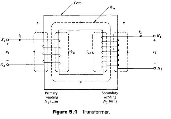
- $\Phi_m$ : Mutual flux, contained within magnetic core that links all the turns of primary, secondary windings
- $\Phi_{l1}, \Phi_{l2}$ : Primary / Secondary leakage flux (Only link primary/secondary circuit itself)
- $X_1, X_2$ : Usually lowvoltage marking notation
- $H_1, H_2$ : High voltage
- $\cdot$ : indicates mutual flux components’ direction. due to current $i_1, i_2’$, tend to add the mutual flux when currents enter the dotted terminals
Ideal transformer
- No losses
- No leakage fluxes
- Magnatic core has infinite permeability
- Practical transformer is close to ideal transformer
- 0.5% order of loss (of the transformer power rating)
- 5% order of leakage fluxes compared to mutual flux
- high permeability of special alloy steels
Calculations on ideal transformer
- Flux linkages : $\lambda_i = N_i \Phi_m$
- Terminal voltages : $v_i = {d\lambda_i \over dt} = N_i {d\Phi_m \over dt}$
- Voltage gain
- $a$ : Transformer turns ratio
- Magnetomotive Force(MMF ; 기자력) : # of turns times current passing thru that line
- $R$ : reluctance of core, works as constant factor btw MMF and flux
- Hopkinson’s Law : $MMF = R \Phi$
- $F = N_1i_1 + N_2 i_2 = R\Phi_m = 0 \times \Phi_m$ (Can neglect Reluctance for infinite permeability)
- To simplify the equation, define $i_2 = -i_2’$
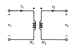
- ABCD parameter representation of ideal transformer
- cf) ABCD for series impedance / shunt admittance
Implementation of physical transformer
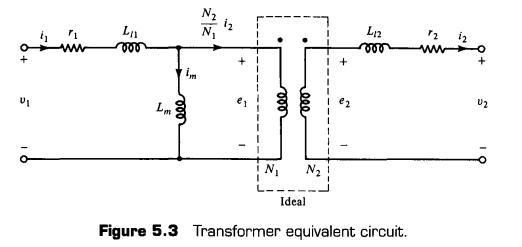
- Considering leakage fluxes
- Leakage inductance can be defined as : $\lambda_{li} = L_i {di_i \over dt}$
- Can get voltage equation
- $r_1, r_2$ : Resistance of primary/secondary winding
Finite permeability
- Suppose $i_2’ = 0$ (case of open circuit) → still $i_m$ (magnetization current) flows
- Can get relationship with $i_1, i_m$ and $i_2’$
- Voltage relation
where magnetizing inductance
\[L_m \triangleq {N_1^2 \over R}\]- Neglecting phenomena of hysteresis and eddy current, (to take care of it, add parallel resistor with $L_m$
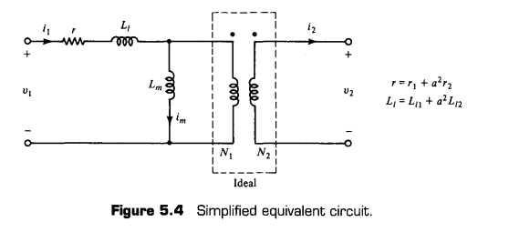
More simplified transformer model
- small value of series impedance, high value of parallel (shunt) impedance can be neglected
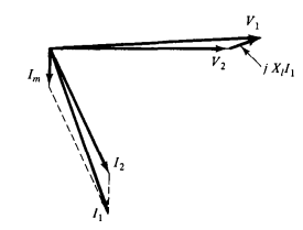
- Phasor diagram for transformer
- For instance, transformer supplies lagging load($I$ lags $V$), the phasor diagram would be like the figure above.
- Using the relationship, $I_m = V_2 / jX_m, I_1 = I_m + I_2, V_1 = V_2 + jX_lI_1$
5.2 Three-phase transformer connections
- Four possible connections : Wye-Wye, Wye-Delta, Delta-Wye, Delta-Delta
- Favored connection : Delta-Wye on with Wye on the high-voltage side.
- High-voltage $Y$ advantages :
- Each winding sees $1/\sqrt 3$ portion of compared to line-line voltage.
- Fewer turns required to provide line voltage
- Neutral point available.
- Ground-fault protection and easy voltage stabilization
- Low-voltage $\Delta$ advantages :
- Provides closed path for triplen-harmonic currents (3x times natural frequency matters)
- Blocks Zero-sequence current from passing
- $\Delta-\Delta$
- No $30^\circ$ phase shift
- Open-delta mode (If one transformer is lost, it still can generate voltage with same phase)
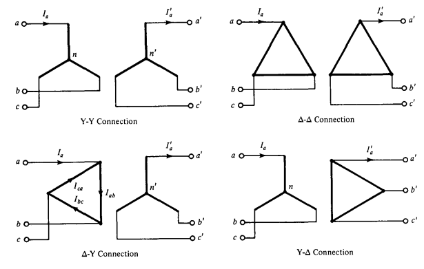
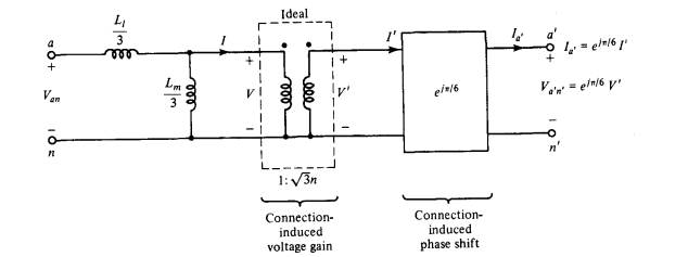
Voltage gain among $\Delta-Y$ connection
- For Wye-Wye, Delta-Delta : Only voltage gain applied (phase unchanged)
- For Wye-Delta, Delta-Wye, we get
- We can seperate complex voltage gain $K_1 \triangleq \sqrt 3 n e^{j\pi/6}$
- For current formula, we get
- Thus, $I’_a = I_a / K_1^*$
- Total complex power conserves
5.3 Per-phase analysis
- Assuming balanced condition and symmetric network, there’s no zero-sequence voltage (or common mode) → Can assume neutral points are at the same potential
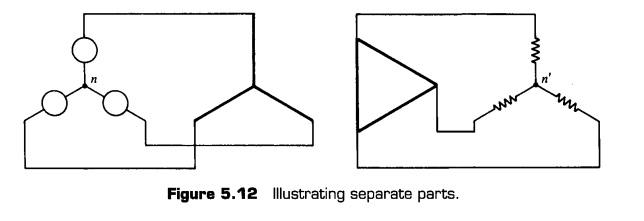
Per-phase diagram (Wye-Wye)
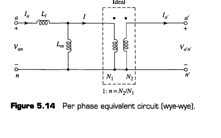
Per-phase diagram (Delta-delta)
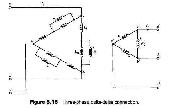
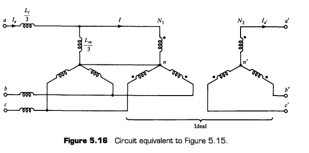
- Two figures above are equivalent circuits
- Can prove two circuits are equivalent by open/shortening secondary circuit
- Secondaries open circuited
- No current flows in secondary circuit (opened)
- No current in primary circuit($I$), Works as voltage division ($L_l +L_m$)
- Using Y-Delta transformation, equivalent branch impedance is $j\omega (L_l+L_m)/3$
- Secondaries short circuited
- No secondary voltage → no primary voltage.
- Primary transformer part is short-circuited → need only to compare $L_l$
- Using Y-Delta transformation, equivalent leakage inductance for Wye is $L_l /3$
Per-phase Diagram (Delta-Wye)
5.4 Normal systems
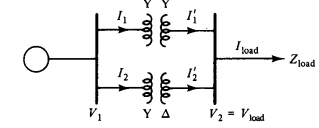
- Large circuling current may occur if transformers are parallely interconnected without matching turn ratios of the transformers
Normal systems
- A system is normal if i the per-phase equivalent circuit, the product of the complex ideal transformer gains around very loop is $1$
- Can be broken down into two sub-conditions (Magnitude / Phase condition)
5.5, 5.6 Per-unit normalization (plus Three-phase quantities)
- Normalize certain quantity by dividing it into base value of quantity
- For three-phase quantities, may also be normalized by picking appropriate three-phase bases
- By defining bases like this, complex power and Voltage per unit is same (Constants cancels out)
5.8 Per unit analysis of normal system
- Pick a voltamphere base for the whole system. (e.g. 10MVA)
- Pick one voltage base (e.g. 138kV)
- Find all impedance bases for the different sections express all impedances in consistent pu terms
- Draw impedance diagram for the entire system.
5.9 Regulating Transformers for Voltage and Phase Angle Control
- Add a small component of voltage, typically less than 0.1 p.u. ( to adjust line or phase voltages)
Voltage-Magnitude regulator
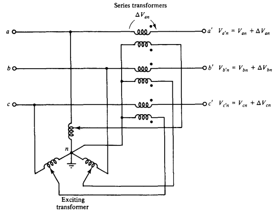
- By adjusting ‘tap’ values in exciting transformer, Can add additional amout of voltage
- Each node gains $\Delta V_{an}$ by passing through transformer
Phase-angle regulating transformer
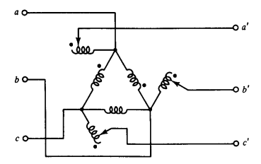
- Windings shown in parallel are the priamry and secondary of single-phase transformer.
- $\rho$ is a small positive number, changed by adjusting tap
- by considering the sign convention
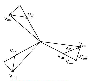
- Resultant phase diagram
Open-circuit voltage ratio mismatch
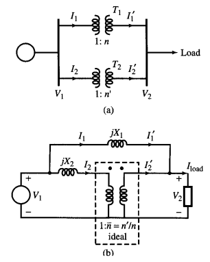
- Can make equivalent circuit with ratio $\bar n = n’ / n$, leaving pu reactance $X_1$
5.10 Autotransformers
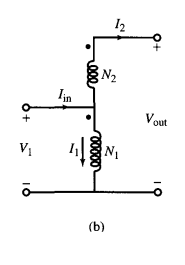
- Primary, secondary windings are electrically connected and mutually coupled.
5.11 Transmission Line and transfomers
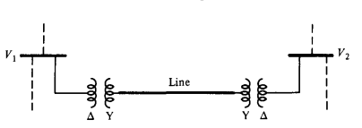
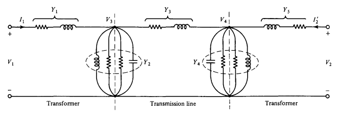
- Transmission line can be modeled as impedance diagram by following :
댓글을 불러오는 중입니다.