
[PSA] Chapter 8 - Generator Modeling
8.0 Introduction
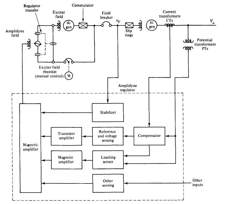
- Exciter : complete voltage control system, including an error detector, feedback loop, automatic voltage regulator(AVR)
8.1 Exciter System Block Diagram
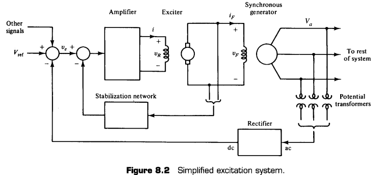
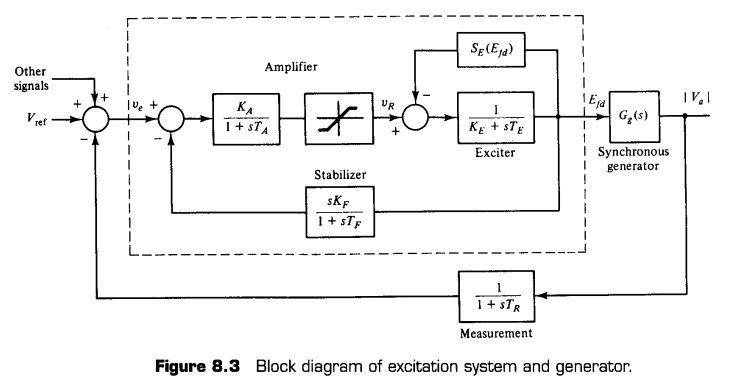
Measurement block
- Gain of measurement block is unity in steady-state
Amplifier block
- Amplifier gain $K_A$ is typically in the range 25 to 400
- $T_A$ in range 0.02 to 0.4 sec
- Amplifier voltage has limitations (exciter field winding can supply limited voltage)
Exciter block
- Voltage of dc generator is proprotional to product of speed times air-gap flux per pole
- Due to saturation effect of magnetic circuit, the flux is a nonlinear function of dc generator field current
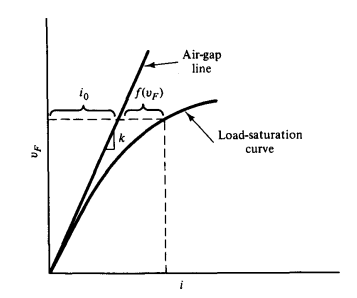
- Consider inverse-relationship between $v_F $ and $i$
- Assume that dc generator output voltage $v_F$ is proportional to dc generator air-gap flux,
- We can get following equation by converting $v_F$ into $E_{fd}$
Where $T_E \triangleq k/R\beta, S(v_F) \triangleq kf(v_F)/v_F$, Saturation function
8.2 Generator Models
Case I : Open Circuit
- $I_a = 0$, we have $E’_a = E_a = V_a$
- Recall relationship between $E’_a $ and $E_{fd}$
We can substitute $E’_a $ with $E_a$
Can get transfer function
\[G_g(s) = {\vert \hat V_a\vert \over \hat E_{fd}}={1\over 1+sT'_{do}}\]Case II : Impedance Load
- Assume that isolated generator supplying an impedance load $Z$.
- By considering relationships,
For inductive loads, $\sigma<1$
Can get desired transfer function by defining some auxiliary variables
\[G_g(s) = {k_v\sigma \over 1+s\sigma T'_{do}}\]Where $k_v \triangleq \vert Z \vert \vert K \vert$, $K \triangleq K_q+jK_d$, $I_d = K_d\vert E’_a \vert, I_q = K_q\vert E’_a \vert$
8.3 Stability of Excitation System
- higher loop gain → smaller voltage error
- but consequently excitation system can be unstable
- Solution : add rate feedback to exciter
댓글을 불러오는 중입니다.