
[PSA] Chapter 2 - Basic Principles
2.1 Phasor Representation
\[\begin{equation} e^{\pm j\theta} = \cos\theta \pm j\sin\theta \tag{2.1} \end{equation}\]- Remark Euler’s identity
- Conventional to use the cosine function in analyzing the sinusoidal steady state
Effective Phasor representation
\[\begin{equation} V = \frac{V_{\max}e^{j\theta_v}}{\sqrt{2}} \tag{2.6} \end{equation}\]- Complex number that carres the amplitude and angle
2.2 Complex power supplied to a one-port
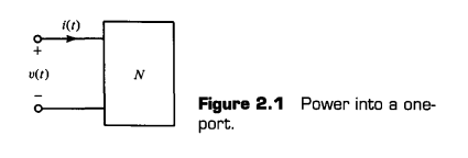
- sometimes we represent phase angle of current and voltage by $\theta_V = \phase{V}, \theta_I = \phase{I}$
- Function of power over time $p(t) = v(t)i(t)$
- Averaged term + sinusoidal compnent of frequency $2\omega$
- Twice as many zero crossings of $p(t)$ as of $v(t) $ or $i(t)$
Power factor angle / Average power over one period
\[\begin{equation}\phi \triangleq \theta_v - \theta_i\tag{2.11}\end{equation}\] \[\begin{equation}\begin{aligned}P&= \frac{1}{T}\int_{0}^{T} p(t)\,dt \\&= \frac{1}{2}V_{\max}I_{\max}\cos\phi\end{aligned}\tag{2.12}\end{equation}\]- Using effective phasors
→ using effective phasors(where $V$ is RMS value of $v(t)$)
- Average power dissipated in a resistor with resistance $R$ connected with effective voltage $V$ = Same equation with DC
Power Factor(PF)
\[\begin{equation}\mathrm{PF}\triangleq\cos\phi\tag{2.16}\end{equation}\]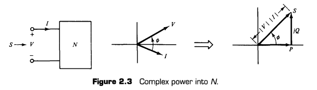
Terminology and descriptive units
- $S$ : Complex power. $[VA, kVA, MVA]$
- $\vert S \vert$ : Apparent power. $[VA, kVA, MVA]$
- $P$ : Average or real or active power. $[W, kW, MW]$
- $Q$ : Reactive power. $[VAr, kVAr, MVAr]$ (r : reactive)
2.4 Balanced Three-phase
- Positive sequence (order of a, b and c) : 0, -120, 120 degree
- Negative sequence (a, c, b) or 0, 120, -120 degree
Wye and delta source
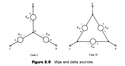
- In case of Case II, assume that $E_{ca}+E_{bc}+E_{ab}=0$ → series resistance is zero, so if not zero, circulating current would be infinite → so make sum of Voltage is zero, current is inderminate(0/0) → assume its circulating current 0
Symmetric three-phase network and neutral voltage
- For every symmetric three-phase network, neutral voltage $V_{nn’}=0$
- when impedence $Z_n$ is connected between two neutrals, $V_{nn’}=0$
Delta-Wye transformation (Symmetrical case)
- For load transformation, $Z_{\lambda} = Z_\Delta /3$ : Use KVL, and KCL
- For source transformation
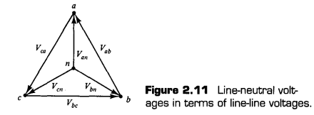
- For positive-sequence,
2.5 Per phase analysis
- Per-phase analysis reduces balanced three-phase network to one.
- Assumption
- balanced three-phase (connected) system
- all loads and sources are wye-connected
- no mutual inductance between phases
- We can say
- all the neutrals have same potential
- phases are completely decoupled (i.e. can be interpreted independently)
- all corresponding network variables occur in balanced sets of same sequence of source (if positive, postive .. i.e.)
- Method of per-phase analysis
- convert all $\Delta$-connection to Y connection
- analyze only phase a circuit
- Subtract 120, 240 degree to get b, c
- Get back to original circuit if necessary
2.6 Balanced Three-phase power
- Instantaneous power delived to a load is constant
- Sum of three phase complex power
- $S_{3\phi}$ is three times of per-phase complex power
댓글을 불러오는 중입니다.