
[PSA] Chapter 11 - Automatic Generation Control and the New Market Environment
11.0 Introduction
- AGC(Automatic generation control) - including
- Load frequency control
- economic dispatch
11.1 Power Control System Modeling
- Speed governor controls generator speed by adjusting steam valve position change
- Linearlizing governor linkage (steam valve position change is proportional to mechanical power change)
- Assuming small perturbation of every term
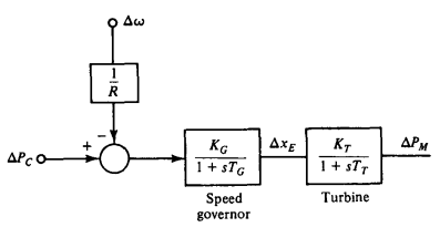
- Setting scaling factor $K_GK_T=1$, We can approximate turbine-govenor model
- For large-signal application, can add saturation that steam valve can move within close and open status
Related Droop Control equation
- For steady state, we can assume $s=0$, $G(0)=1$
- Fixing out power command $\Delta P_c=0$
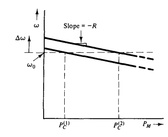
- $R$ : Regulation, $1/R$ : Gain in governor block ($\Delta \omega \rightarrow \Delta P_M$)
11.2 Application to single machine-infinte bus system
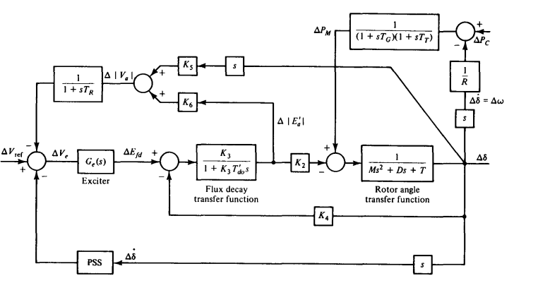
- With speed governor, $\Delta P_M$ depends on $\Delta \omega$, $\Delta P_C$
11.3 Simplified Analysis of Power control system
- Two inputs : $\Delta V_{ref}$, $\Delta P_C$,
- Can take two outputs : $\Delta \vert V_a \vert$ and/or $\Delta \delta$
- If we are interested in transient analysis, we can completely ignore power control loop (since the feedback is too slow to react to transient change) (i.e. $\Delta P_M=0$)
- If we are interested in stpe response to $\Delta P_C$, with $\Delta V_{ref}=0$, we can easily leave out voltage control loop systems
11.4 Power control, Multigenerator case
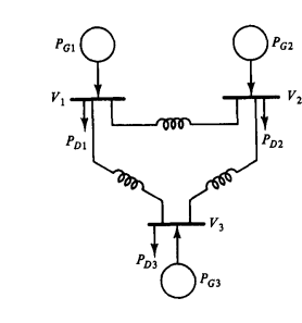
- At each bus,
- Assume an operating point,
Then we can get relationship between increment happening near operating point
\[\Delta P_{Gi} = \Delta P_{Di}+\Delta P_i\tag{11.10}\]If we consider linearized model of swing equation,
\[M_i\Delta\ddot\delta_i + D_i \Delta \dot \delta_i + \Delta P_{Gi} = \Delta P_{Mi} \tag{11.11}\]We can also linearize $P_{Di}$. Affected by both frequency and voltage magnitude, we can assume there’s no voltage magnitude change → no need to consider
- For small changes in frequency, we assume that
- $\Delta P_{Li}$ : External load added / removed (externally imposed load disturbance) (e.g. switching electronics)
- For Phase $a$, instantaneous voltage is
- $\omega_0 $ : Nominal frequency, $2\pi60$
- $\theta_i^0$ : angle of bus $i$ at operating point compared to slack bus
- Taking time derivative of the argument of the cosine function,
Thus
\[\Delta \omega_i = \omega_i-\omega^0 = \Delta \dot \theta _i \tag{11.15}\]Define $D_{Li} \triangleq \partial P_{Di}(\omega^0) / \partial \omega_i$,
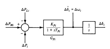
\[\Delta P_{Di} = D_{Li}\Delta\dot \theta_i + \Delta P_{Li} \tag{11.16}\] \[M_i\Delta \ddot \delta_i + D_i\Delta \dot \delta_i + D_{Li} \Delta \dot \delta_i + \Delta P_{Li} + \Delta P_i = \Delta P_{Mi} \tag{11.17}\]- To calculate $\Delta P_i$, Assume that line admittance parameters are purely imaginary (lossless), get
With the same method above, define operation quantities and express them with delta
By simple trigonometry,
\[\begin{aligned} P_i^0+\Delta P_i = \sum_{k=1}^{n}|V_i||V_k||B_{ik}| \Big[ &\sin(\theta_i^0-\theta_k^0) \cos(\Delta\theta_i-\Delta\theta_k) \\ +&\cos(\theta_i^0-\theta_k^0) \sin(\Delta\theta_i-\Delta\theta_k) \Big] \end{aligned} \tag{11.19}\]- Assuming small angle difference, $\cos{(\Delta\theta_i - \Delta \theta_k)}\approx 1, \sin(\Delta \theta_i-\Delta \theta_k) \approx \Delta\theta_i-\Delta \theta_k$
- Define Stiffness / Synchronizing Power Coefficient
Then
\[\Delta P_i = \sum_{k=1}^n T_{ik} (\Delta \theta_i-\Delta\theta_k) \tag{11.21}\] \[T_{ik} = \frac{\partial P_i} {\partial(\theta_i-\theta_k)}\]- $T_{ik}$ : power flow stiffness or sensitivity against angle difference
- We can assume $\Delta \delta_i = \Delta \theta_i$ for small angle change, we can express
- Merge two coefficients, $\tilde D_i \triangleq D_i + D_{Li}$
- $M_i \Delta \ddot \delta_i$ : Power required ofr rotor acceleration
- $\tilde D_i \Delta \dot \delta_i$ : Damping effect of generator and load
- $\Delta P_i$ : Emitting power to the transmission network
- $\Delta P_{Mi}$ : Delta of turbine mechanical power
댓글을 불러오는 중입니다.